Principle of operation: Flow control servovalves
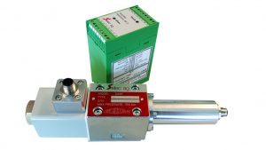
A servo valve that is simple, rugged in design and dependable in performance to give superior system control and long trouble free operation.
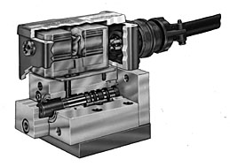
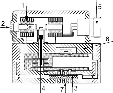
1. Double air gap low DC current dry torque motor (130 ma standard others available)
- Extremely stiff and well dampened to achieve the best dynamic properties.
- Large encapsulated coils provide a very stable and rugged magnetic system.
- Torque motor is isolated from and not contaminated by the fluid.
- Can be used with high water content fluids.
- There is no mechanical connection between the magnet system and the power spool.
2. External null adjustment
- Easy accessibility for fine tuning valve.
3. Integral 55 micron filter screen
- Protects orifices and nozzles from contamination and resulting performance degeneration.
- Easily accessible
4. Power spool with integral force amplifier
- Feedback of the second stage (power) spool is provided by the unique patented design which throttles the nozzles mounted within the spool. This design eliminates the need for a cantilever feedback spring and long control passages in the second stage spool control areas. The short symmetrical pilot lines improve frequency response while the elimination of the feedback spring results in high reliability.
- The control edges of the power spool and cylinder are hardened, ground and lapped.
5. Rugged electrical connections
- A simple easy to plug-in electrical connection using four pin MS receptacle and mating connector plug with cable clamp and boot is standard.
6. Rugged stainless steel body
- Resists corrosion (Compatible with high water content fluids)
7. Standard NFPA (CETOP) mounting patterns
- Mounts on standard sub-plates or bar manifolds
- Can replace low performance proportional
8. Selec servo valves can be driven by Selec ’s standard amplifier for superior performance, but they can also be driven by amplifiers manufactured by others.
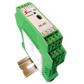
- Rail-mounted amplifier for servo or proportional solenoid controlled valves.
- Built-in flow, pressure, pressure and horsepower limiting, and load sense program configurations.
- Closed-loop control for a single valve.
- Built-in password protected parameter and program setup valves
LVDT (3rd-stage valves only)
- A linear variable differential transformer (L.V.D.T.) is used to monitor the position of the main spool on a three-stage valve.
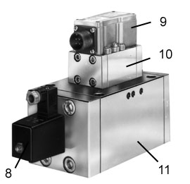
9. Torque motor/flapper primary stage
10. Second Stage
- Power spool is pilot for the three-stage valve
11. Third Stage
- Has a Linear Variable
Differential Transformer (L.V.D.T.) for feedback.
Selec’s extensive application experience
- Selec is a hydraulic equipment manufacturer totally dedicated to microelectronic control systems.
- Electronics is integrated in Selec’s hydraulic engineering as a integral part of the engineering department. CAD/CAM insures optimal system design incorporating the latest developments.
- Selec has been an electrohydraulic manufacturer since 1969 and will be there if you need help in the future.
Performance assurance is standard with every Selec component
The total dedication to performance is based upon experience gained since 1969 in matching fluid power equipment to a tremendous variety of machines and applications.
Selec’s Performance Assurance is made possible because of experience gained over the years in supplying machinery builders and users with unique solutions to thousands of unusual fluid power problems. Historically, Selec has concentrated its energies on hydraulics and electrohydraulic equipment and systems.
Principle of operation
Two-Stage Servo Valves
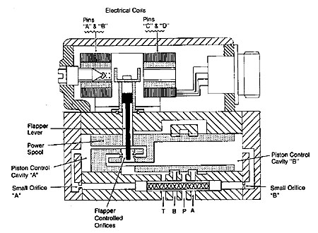
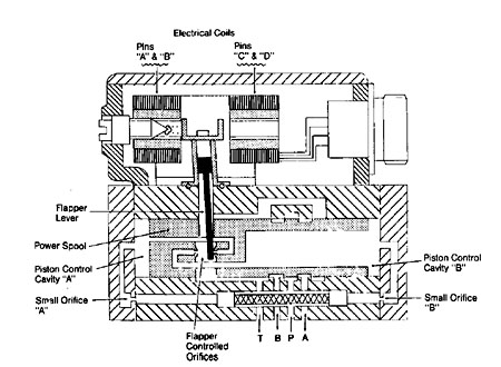
The primary stage of a two stage servo valve, shown in Figure “A”, is a current driven device. Current in the coils produce a magnetic field which deflects the flapper lever an amount proportional to the current level and in the direction consistent with the direction of current flow.
The movement of the flapper lever upsets the pressure balance positioning the power spool. The power spool then repositions in the direction of the flapper lever so the pressure balance is again maintained.
Although the power of the flapper lever is very small, the hydraulic force amplification generated on the piston control cavities “A” and “B” is enough to accurately position the power spool.
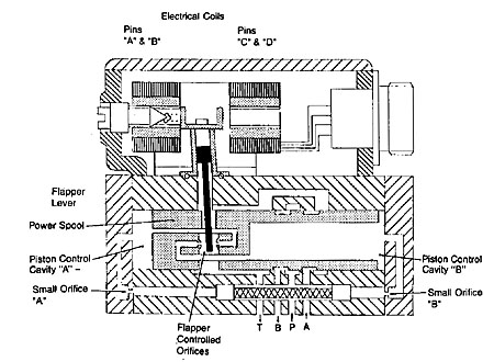
If a positive current flows from pin “A” and “C” to pin “B” and “D”, the flapper lever will move to the right as shown in Figure “B”. This movement of the flapper effectively throttles the nozzle on the right while de-throttling the nozzle on the left. The result is a pressure increase in cavity “A” which is supplied with fluid from the pressure port thru the small orifice “A”. At the same time, the pressure in cavity “B” decreases as it is opened to tank “T” (drain).
The pressure imbalance moves the power spool to the right until the flapper controlled nozzle gaps are equal and pressure in cavities “A” and “B” are once again equal as shown in figure “C”. The repositioning of the power spool will result in pressure port “P” being connected to control port “B” and control port “A” connected to tank or drain port “T”.
By reversing the DC current direction from the above example, the flapper and main spool will move to the left and port “P” will be connected to control port “A” and control port “B” connected to tank “T” (drain).
Three-Stage Servo Valves
In the three-stage servo valve, the pilot valve is a standard VSC4-R03 two stage servo valve. This pilot valve directs fluid flow to position the third stage power spool. A Linear Variable Differential Transformer (LVDT) attached to the third stage generates an electrical feedback signal proportional to spool movement. The electronic package controlling the valve must supply the excitation for the LVDT as well as the signal conditioning circuitry for summing the feedback signal with the command. The standard Selec Amplifier Module provides all these functions.
When an error exists between the command signal and the conditioned LVDT feedback signal, the amplifier produces an output current to the two-stage pilot valve. This pilot valve in turn ports fluids to and from piston cavity areas “C” and “D” to shift the third stage spool. As the third stage spool moves, the LVDT feedback signal will change accordingly to cancel the command signal.
When the sum of the command voltage and the feedback volt is zero, the current output of the amplifier will also be zero. The result is the centering of the pilot valve. The pressure in piston control cavity “C” and “D” will be equal and the third stage spool will be at a new offset stable position.
If the error signal between the command and feedback signal was opposite in polarity, the valve would shift in the opposite direction. The polarity and amplitude of a command voltage determines the direction and magnitude of spool offset and flow.

